Table of Contents: WCB Standards
WCB Standard: G601 Heavy Duty Backstops for Logs and Rocks
WCB Standard: G602 Log Loader and Log Yarder Raised Cabs
WCB Standard: G603 Heavy Duty Guards for Windows
WCB Standard: G604 Light Duty Guards for Windows
WCB Standard: G605 Mobile Equipment Half-Doors
WCB Standard: G606 Boom Boat Operator Protective Structures
WCB Standard: G607 Medium Duty Screen Guard (Front End Log Loader)
WCB Standard: G608 Mobile Equipment Roof Structures — Heavy Duty
WCB Standard: G609 Mobile Equipment Roof Structures — Light Duty
Schedule 4-A WorkSafeBC Standard — Guardrails Using Rope or Other Non-rigid Material
WCB Standard: LDR 1-2004 Job Built Ladders
WCB Standard: PPE 1 — 1997 Leg Protective Devices
* Only applies to leg protection devices manufactured prior to February 1, 2011.
Schedule 8-A WorkSafeBC Standard — Leg Protective Devices
Applies to leg protection devices manufactured after February 1, 2011.
WCB Standard: PPE 2 High Visibility Garment — Personal Protective Equipment Standard 2
WorkSafeBC Standard 13.30 Work Platforms Supported by Lift Trucks
WCB Standard: A324 Forklift Mounted Work Platforms
* Only applies to platforms built prior to April 1998
Schedule 14-A WorkSafeBC Standard 14.116 Chimney Hoists
WCB Standard: WPL 1-2004 Design, Construction and Use of Wood Frame Scaffolds
WCB Standard: WPL 2-2004 Design, Construction and Use of Crane Supported Work Platforms
WCB Standard: WPL 3-2004 Safety Factor and Minimum Breaking Strength for Suspended Work Platforms and Associated Components
Retired Standards
The following WCB standards have been retired:
WCB Standard: A321 Self-Propelled Elevating Work Platforms has been replaced by CSA Standard CAN3-B354.3-M82, Self-Propelled Elevating Work Platforms for Use as "Off-Slab" Unit and CSA Standard CAN3-B354.2-M82, Self-Propelled Elevating Work Platforms for Use on Paved/Slab Surfaces
WCB Standard: A322 Elevating Rolling Scaffolds has been replaced by CSA Standard CAN3-B354.1-M82, Elevating Rolling Work Platforms
WCB Standard: A323 Work Platforms Mounted on Industrial Lift Trucks has been replaced by ANSI Standard ASME B56.1-1993, Safety Standard for Low Lift and High Lift Trucks
WCB Standard: A326 Design, Construction and Use of Suspended Platforms
WCB Standard OFA1: Certification of Occupational First Aid Attendants has been replaced by OHS Guidelines G3.15(b)-1 to G3.15(c), G3.17.1 and G3.21(2).
WCB Standard: PPE 14.1 Leg Protection For Chain Saw Users (Agricultural Operations only)
WCB Standard: G601 Heavy Duty Backstops for Logs and Rocks
See Schedule 16-A in Part 16 of the OHS Regulation.
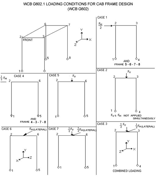
WCB Standard: G602 Log Loader and Log Yarder Raised Cabs, March 1990
© Workers' Compensation Board of British Columbia. All rights reserved. No part of this document may be copied, reproduced, or distributed for profit or other commercial enterprise, nor may any part be incorporated into any other publication, without written permission of the Workers' Compensation Board of B.C.
1. General
1.1. ScopeThis standard pertains to log loaders and log yarders, and other mobile equipment where the operator may be exposed to hazard caused by intruding or flying objects, such as whipping cables, loose debris, snags, tree trunks, limbs, etc. It is supplementary to G601 Standard for Log Loader and Log Yarder Backstops, and is supplemented by G603 Standard for Log Loader and Log Yarder Window Guards.
1.2. Purpose
This standard is intended to describe the minimum requirements for the design and selection of plates, framework and supports for raised cabs on equipment without a backstop. This will form and provide a protective structure for the operator inside the cab.
2. Design Principles and Assumptions
The following points are stated to clarify the underlying principles and assumptions of this Standard.
2.1.
A static force resistance design criteria is stipulated to ensure that intruding or flying objects will not deflect the cab beyond a certain limit.
2.2.
Also included is an energy design criterion, since in an actual situation involving flying objects, loading will be dynamic and possibly impact. Hence the adequacy of the structure is related more to energy absorption capability and details of weld design and welding procedure rather than static strength.
2.3.
The recommended design horizontal and vertical force will not necessarily duplicate the force imparted by an actual flying object such as trees, whipping cables, etc.
2.4.
As the cab elevation is increased, the vertical load requirement § 3.1.1 may be reduced accordingly.
2.5.
It is assumed that if the cab/structure can resist a force of W (Appendix A), then it will have adequate resistance to whipping cables. A magnification factor has been incorporated into the formulae to compensate for very small logs, because in such cases, other factors such as flying debris or cables may govern. In any case, W used for design purposes should not be less than 9000 N (2000 lb).
2.6.
Although cabs meeting these criteria may not deflect within the Deflection Limiting Volume (DLV See SAE J397a) under all circumstances, it is a minimum requirement for the Cab Protective Structure to have a "Crush Protection" design capability to withstand the force exerted on it by a hypothetical blunt log striking end-on at a velocity of 11 km/hr.
2.7.
Furthermore, there is an impact or strength requirement which is intended to ensure that all members of the cab will have adequate resistance to brittle fracture under cold temperatures.
2.8.
Finally, there is a visibility requirement which is to ensure that the operator's vision will not be seriously obstructed.
2.9.
The operator protective structure can be an integral part of a cab or can be a "cage" outside an existing cab. Hereinafter the term "Cab Protective Structure" shall mean any guard that envelopes the cab or any guard that forms part of a cab. (See Appendix D.)
3. Design Loads
3.1. Vertical Load Requirement
| Force Resistance | Fv = | 2.5 x Wxi | units N, m |
| H | |||
| Fv = | 8.25 x Wxi | units lb, ft | |
| H |
H = distance from grade to top of Cab Protective Structure.
W = weight of log handled as defined in Appendix A.
Fv = vertical equivalent static force.
i = impact factor as defined in Appendix B or other acceptable method.
|
Energy Absorption |
Ev = 0.152 W |
units N, J |
|
Ev = 6W |
units lb, lb-in |
Ev = ultimate energy to be absorbed by the frame at the point of impact. (J), (lb-in).
3.2. Lateral Load Requirement
FL = equivalent lateral static force, where FL is greater than the tipping force, then FL may be reduced to that of the tipping force.
4. Design Requirements
4.1. Frame
4.1.1
All frame members of the Cab Protective Structure shall be designed to resist the applied load in accordance with Appendix C or with some other acceptable design criteria to the Board.
4.1.2
In addition, the frame shall be designed to absorb the impact energy as given by Ev and EL of § 3.1.1 to § 3.1.2.
4.2. Cab Skin
All exposed unguarded sides of the cab should be protected with metal plates
or other suitable material. They shall be designed to resist the FL as defined in § 3.1.2.
4.3. Supports
The cab protective structure shall be secured to the structural parts of the (carrier) main frame of the log loader or log yarder. Such structural parts shall be adequately reinforced if necessary to resist the loads imposed on them by the cab protective structure.
4.4. Fastenings
If bolts and nuts are used in the fabrication of the guard, they shall conform to or exceed the ASTM Designation A325 Requirements.
4.5. Visibility Requirements
The cab shall be equipped with adequate view areas. All such view areas shall be guarded in accordance with WCB G603 Standard for Log Loader and Log Yarder Window Guards.
4.6. Impact Strength Requirement
All members of the guard shall be made of material with good impact absorbing properties. The following guideline may be used:
Examples of steel meeting or exceeding the above requirements:
- ASTM A36, CSA G40.21 33G, 44W - for plates, bars and angles.
- CSA G40.21 50W - for HSS. (Hollow Structural Sections)
4.7. Weldment
Weldments shall conform to applicable sections of General Specification for Welding of Steel Structures, CSA W59.1-1970 (or latest revision thereof) and shall be performed by licensed welders only.
4.8. Alternate Exit
The operator protective structure shall be provided with an alternate exit. Such exit shall have a minimum clear opening of 60 cm diameter (24").
4.9. Glazing
Only safety glass or other suitable material with similar shatter-resistant characteristics shall be used for window areas.
4.10. Sound Isolation and Absorption
The cab interior shall have a sound level reading of not more than 80 db under normal working conditions and with all openings closed. Flammable sound absorption material should be avoided.
APPENDIX "A"
Derivation of W.
The symbol "W" represents weight of the heaviest log expected to be handled by the log yarder or loader. For the purpose or this standard, g (density of logs) should be assigned a value of 560 kg/m3 (35 pcf) which is the arithmetic mean of the common species found in B.C. The following formula may be used to compute the expected weight of incoming logs:
DB = butt end diameter m, ft.
DT = top end diameter m, ft.
L = average length of logs handled, m, ft.
g = density of logs handled kg/m3, pcf.
APPENDIX "B"
Impact Factor* (i)
v = velocity of approaching log.
ΔST = static deflection of guard member due to weight of approaching log.
g = acceleration due to gravity (32 ft/sec2 or 9.8m/sec2).
* Other acceptable method may be used.
APPENDIX "C"
WCB Standard: G603 Heavy Duty Guards for Windows
See Schedule 16-B in Part 16 of the OHS Regulation.
WCB Standard: G604 Light Duty Guards for Windows
See Schedule 16-C in Part 16 of the OHS Regulation.
WCB Standard: G605 Mobile Equipment Half-Doors, March 1990
© Workers' Compensation Board of British Columbia. All rights reserved. No part of this document may be copied, reproduced, or distributed for profit or other commercial enterprise, nor may any part be incorporated into any other publication, without written permission of the Workers' Compensation Board of B.C.
1. General
1.1. Scope
This standard pertains to any rubber-tired skidders employed in the skidding of logs or tree lengths where the operator may be exposed to flying or other intruding objects.
1.2. Supplementary References
This standard is supplemented by G604 WCB Standard for Light-Duty Screens.
1.3. Purpose
This standard is intended to describe the minimum requirements for the design
and selection of structural elements such as plates, stiffeners, sheer deflectors,
spring latches or hinges for the half-door.
2. Design Requirements
2.1. General Location
A half-door shall be installed on both side entrances to the control area.
2.2. Dimensions
2.2.1
The entrance opening width shall be a minimum of 46 cm (18 inches). Recommended
opening width is 70 cm (27 inches).
2.2.2
The door height shall be a minimum of 60 cm (25 inches) from the floor and having
the top of the door at least 25 cm (10 inches) above the cab seat.
2.3. Character (Distinctive Qualities)
2.3.1
The half-door should not sweep the area of the platform or the steps on which
the operator must stand to open the door. It shall sweep outward from the cab.
2.3.2
The half-door shall be equipped with a device to cause it to return to its closed
position automatically. Also, a latch, preferably of pressure sensitive type
should be used to lock the door.
2.3.3
There should be sufficient clearance between the maximum radius of door sweep
and the rubber tires of the mobile equipment.
2.3.4
A sheer deflector or stiffener shall be installed on the exterior top edge of
the door to act as a deflector/stopper for objects propelled upward.
2.4. Static Strength
2.4.1
The top edge of the door shall be reinforced by a ledge, (sheer deflector),
a structural element capable of withstanding a concentrated force of 17800 N
(4,000 lbs.) applied at 45° to the horizontal.
2.4.2
Any area of the door shall be designed to resist a 17800 N (4000 lb) static
force applied over an area of 62 cm2 (9.6 in2).
2.4.3
The hinges, stops and supports shall be adequately designed and fabricated to
resist any loads that the door would likely impose upon them. The entire door
assembly shall be designed to resist a static force of 17800 N (4,000 lbs.)
without causing the door to spring open. On vehicles equipped with a ROPS (Rollover Protective Structure), the
door-supporting elements may be attached to parts of the ROPS providing such
attachment does not adversely affect the performance of the ROPS. This is contingent
on approval by a registered professional engineer.
2.4.4
Weldments shall conform to applicable sections of General Specifications for
Welding of Steel Structures CSA W59.1-1970 or most recent version and should be performed by qualified
welders only.
2.5. Impact Strength Requirement
All members of the half-door shall be fabricated of material with good impact
absorbing properties. The following guideline may be used:
- Low carbon content - maximum .28%
- High manganese-carbon ratio
- Low phosphorus content
- Fine grain size
- Heat treated
- High ultimate energy resistance (Notch tough steel possessing acceptable impact properties)
Examples of steel meeting or exceeding the above requirements:
- ASTM A36 or CSA G40.21-38W - for bars, angles and plate
- CSA G40.21 42W, 55W - for HSS (Hollow Structural Sections) (CSA G40.16 and G40.17)
3. Structural Details Guidelines
The following recommendations may be used in lieu of clause 2.4.1 and clause 2.4.2
3.1.
Minimum ledge beam size shall be 2 x 2 x .188 HSS, CSA G40.21 42W.
3.2.
Door - steel plate 5 mm (3/16") minimum.
3.3.
Minimum intermediate stiffener size shall be L 2 x 2 x 3/16 CSA G40.21 33W.
3.4.
Maximum spacing of stiffeners is six inches, when L 2 x 2 x 3/16 is used.
WCB Standard: G606 Boom Boat Operator Protective Structures, March 1990
© Workers' Compensation Board of British Columbia. All rights reserved. No part of this document may be copied, reproduced, or distributed for profit or other commercial enterprise, nor may any part be incorporated into any other publication, without written permission of the Workers' Compensation Board of B.C.
1. General
1.1. Scope
This standard pertains to any vessel used to push or pull logs, booms, bundles
or bags in booming ground operation where the operator may be exposed to collision
with water-borne logs. Examples of such vessels are dozers, side winders, boom
scooters and tugs.
1.2. Purpose
This standard is intended to describe the minimum requirements for the design
and selection of window guards, plates, framework and supports for a cab which
will form and provide a protective structure for the operator occupying same.
2. Design Principles and Assumptions
The following points are stated to clarify the underlying principles and assumptions of this standard.
2.1.
The stiffness of the vessel is assumed to be in direct proportion to W x GM
x SIN q were W is the weight of vessel, GM is the metacentric height, and
q is the angle of heel.
2.2.
The stiffness of the operator protective structure is assumed to be very much
higher than the vessel's heeling resistance. Hence the stiffness of the entire
system is approximately equal to the heeling resistance of the vessel.
2.3.
It is assumed that the elements of the operator protective structure would be
arranged in such a way to elastically deflect the projectile rather than arresting
its motion.
2.4.
The derivation of the peak collision force is based on linear elastic collisions.
2.5.
It is a minimum requirement for the protective structure to have a "crush protection
design capability" to withstand the force exerted on it by a hypothetical blunt
log 1 m x 12 m (3 feet x 40 feet) striking end-on at a velocity of 1.5 m/s (5
fps).
Furthermore, there is an impact or strength requirement which is intended to ensure that all members of the cab will have adequate resistance to brittle fracture under cold temperatures.
2.6.
Finally, there is a visibility requirement which is to ensure that the operator's
vision will not be seriously obstructed.
2.7.
The operator protective structure can be an integral part of a cab or it can
be a "cage" outside an existing structure.
3. Design Loads
3.1.
Imperial Units
3.2.
Metric Units
W = weight of vessel, lbs. or N.
CM = distance from metacentric to hypothetic point of impact, ft. or meters, CM must not be less than 2.1 m (7 ft.).
F = dynamic design load, lbs. or N, less than or equal to the capsizing force.
4. Design Requirements
4.1. Frame
All frame members of the cab protective structure shall be designed to resist
the applied load in accordance with clause 3.0 or with some other design criteria
acceptable to the Board.
4.2. Cab Skin
All exposed unguarded sides of the cab shall be protected with metal plates
or other suitable material. They shall be designed to resist the force as defined
in clause 3.0.
4.3. Supports
The cab protective structure shall be secured to the structural parts of the
vessel. Such structural parts shall be adequately reinforced to resist the loads
imposed on them by the cab protective structure.
4.4. Fastenings
If bolts and nuts are used in the fabrication of the guard, they shall conform
to or exceed the ASTM designation A325 requirements.
4.5. Visibility Requirements
The cab shall be equipped with adequate view areas. All such view areas shall
be guarded by vertical members spaced at intervals of not more than 6 inches.
These vertical members shall be designed to assist the force as defined in clause
3.1.
If flat bars are used as vertical elements, they should be in a radiating pattern to minimize interference with the operator's line of sight.
4.6. Impact Strength Requirement
All members of the half-door shall be fabricated of material with good impact
absorbing properties. The following guideline may be used:
- low carbon content - maximum .28%
- high manganese - carbon ratio
- low phosphorous content
- fine grain size
- heat treated
- high ultimate energy resistance (Note: tough steel possessing acceptable impact properties)
Examples of steel meeting or exceeding the above requirements:
- ASTM A36 or CSA G40.21 - 38W for bars, angles and plate
- CSA G40.21 42W, 55W for HSS (Hollow Structural Sections) (CSA G40.16 and G40.17)
4.7. Weldment
Weldments shall conform to the applicable sections of general specifications
for welding of steel structures, CSA W59.1-1970(or latest revision thereof)
and shall be performed by licensed welders only.
4.8. Alternate Exit
The operator protective structure shall be provided with an alternate exit.
Such exit shall have a minimum clear opening of 60 cm (24 inch) diameter.
4.9. Glazing (optional)
Only safety glass or other suitable material with similar shatter-resistant
characteristics shall be used for window areas and such glazing materials shall
be positioned at least 20 cm (4 inches) away from the window guard.
5. Minimum Sizes
The following recommended sizes and dimensions may be used in lieu of the design load criteria, clause 3.0.
5.1.
Minimum grid element size shall be 3/4" diameter steel rods or equivalent where
a 1 1/4 x 1 1/4 x 0.10 HSS intermediate stiffener is used.
5.2.
Grid element size shall be proportionately increased as the dimension of the
guard increases.
5.3.
Minimum column size shall be 3 x 3 x 0.125 HSS depending on the slope and length
of the columns. 3 x 3 x 0.25 HSS is strongly recommended.
5.4.
Minimum roof beam size shall be 3 x 3 x 0.125 HSS.
5.5.
Minimum "cab skin" plate size shall be 11 ga to 16 ga depending on the size
of intermediate stiffeners used.
5.6.
Gusset plates shall be incorporated where necessary.
5.7.
Materials with equal or better properties may be used in place of those stipulated
in this Standard.
G606A BOOMBOAT O.P.S.

G606B TOWBIT GUARD
WCB Standard: G607 Medium Duty Screen Guard (Front End Log Loader), March 1990
© Workers' Compensation Board of British Columbia. All rights reserved. No part of this document may be copied, reproduced, or distributed for profit or other commercial enterprise, nor may any part be incorporated into any other publication, without written permission of the Workers' Compensation Board of B.C.
1. General
1.1. Scope
This standard pertains to front end log loaders - mobile machines mounted on
a wheeled or tracked chassis, equipped with a front mounted grapple, tusk, or
fork-lift device and employed in the loading, unloading, stacking, sorting or
handling of logs, used only in dry land sorting areas. For other applications,
please refer to G603 Standards for Log Loader and Log Yarder Window Guards.
1.2. Purpose
This standard is intended to describe the minimum requirements for the design
and selection of rod-size, framework and supports for guards over window areas
of operator's cab.
2. Location of screen guards
2.1.
Front screen guard shall be provided in the area in front of the operator and
shall at least extend the full height of all glazing surfaces.
2.2.
Rear screen guard, where necessary and applicable, shall be provided in the
area behind the operator.
2.3.
All guards shall be positioned at least four inches away from the glazed windows.
3. Design Requirements
3.1. Strength Requirements
3.1.1 Grid Element
Each vertical element shall be designed to withstand a minimum concentrated
point load of 300 lbs. being applied at a location producing the greatest critical
stresses. There should be at least three vertical elements.
3.1.2 Perimeter Frame
The outer frame shall consist of sections with the following section modulus:
S = edge beam section modulus (cm3) (in3)
W = dimension of guard (cm) (in)
f = allowable working stress MPa (psi)
3.1.3 Supports
The perimeter frame shall be secured to the structural parts of the cab. Such
structural parts shall be adequately designed and constructed to resist all
loads imposed on them by the guards.
On the front end loaders equipped with a rollover protective structure (ROPS), the screen guards may be attached to parts of the ROPS, provided that such attachment does not adversely affect the performance of the ROPS. All such attachments shall be clamped unless welding is permitted by the ROPS manufacturer or a registered professional engineer.
3.1.4 Fastenings
If nuts and bolts are used in the fabrication of the guard, they shall conform
to or exceed the ASTM Designation A325 requirements.
3.2. Impact Strength Requirement
All members of the guard shall be made of material with good impact absorbing
properties. The following guideline may be used:
- Low carbon content (less than 0.28%)
- High ratio of manganese to carbon
- Low phosphorous content
- Fine grain size
- Heat treated
- High ultimate energy resistance
Examples of steel meeting or exceeding the above requirements:
- ASTM A36, CSA G40.21 33G, 44W - for plates, bars and angles.
- CSA 40.21 50W - for HSS (Hollow Structural Sections)
4. Visibility Requirement
Minimum interference with operator's visibility shall be one of the governing
criteria in the design and positioning of the vertical members of the guard.
If flat bars are used as grid elements, they should be in a radiating pattern
in line with the operator's line of sight. The clearance between vertical elements
shall not be greater than eight inches.
5. Minimum Recommended Sizes
- Vertical elements cross-section size should not be less than 19 mm (3/4") diameter mild steel rod or 16 mm (5/8") square rod.
- The openings between adjacent vertical members should not be greater than eight inches.
- The perimeter frame cross-section size should not be less than 2 x 2 x .150 square hollow structural section (HSS) 50,000 psi yield or 3 x 3 x 5/16 square angle, 36,000 psi yield.
6. Weldment
Weldments shall conform to applicable sections of General Specification for
Welding of Steel Structures, CSA W59.1-1970 (or latest revision thereof) and
shall be performed by licensed welders only.
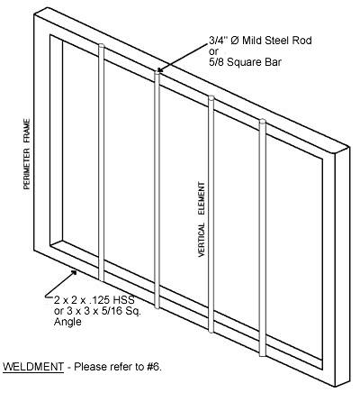
Typical Design
For Illustration Only
WCB Standard: G608 Mobile Equipment Roof Structures - Heavy Duty, March 1990
© Workers' Compensation Board of British Columbia. All rights reserved. No part of this document may be copied, reproduced, or distributed for profit or other commercial enterprise, nor may any part be incorporated into any other publication, without written permission of the Workers' Compensation Board of B.C.
1. General
1.1. Scope
This standard pertains to mobile industrial or logging equipment where the operator
may be exposed to hazards caused by falling objects such as tree trunks, snags,
limbs, rocks, etc. It is also supplementary to G602 Standard for Log Loader and Log Yarder Raised Cabs.
1.2. Purpose
This standard is intended to describe the minimum requirements for the design
and selection of plates and stiffeners for roof construction. Refer to the aforementioned
G602 Standard for details on substructure construction.
2. Design Criteria
2.1. Option One - Testing Method
The roof shall be designed to meet the Minimum Performance Criteria for Falling
Object Protective Structure (FOPS) - SAE J231.
2.2. Option Two - Analytical Methods
The roof shall be designed to absorb 11500 J (8,500 ft-lb) of impact energy
without allowing a projectile measuring 20 cm (8 in) in diameter to penetrate
into the DLV as defined in SAE J397a.
2.3. Option Three - Minimum Recommended Size
The roof shall be designed in accordance with the minimum recommended size as
outlined in §4.0.
3. Design Requirements
3.1. Superstructure of Roof
The superstructure shall be designed in accordance with the design criteria
as outlined in §2.0.
3.2. Substructure of Roof
All frame members and supports of the Cab Protective Structure shall be designed
to resist the applied load in accordance with G602. This applies to all mobile
equipment covered by G602. Equipment covered by SAE J1040 shall be designed in accordance with SAE J1040 or its equivalent.
3.3. Alternate Exit
The operator protective structure shall be provided with an alternate exit.
Such exit shall have a minimum clear opening of 60 cm (24 in) diameter.
3.4. Impact Strength Requirement
All members of the guard shall be made of material with good impact absorbing
properties. The following guideline may be used:
- Low carbon content (less than 0.28%)
- High ratio of manganese to carbon
- Low phosphorous content
- Fine grain size
- Heat treated
- High ultimate energy resistance
Examples of steel meeting or exceeding the above requirements:
- CSA G40.21 33G, 44W - for plates, bars and angles
- CSA G40.21 50W - for HSS (Hollow Structural Sections)
3.5. Weldments
Weldments shall conform to applicable sections of General Specification for
welding of Steel Structures, CSA W59.1-1970 (or latest revision thereof) and
shall be performed by licensed welders only.
4. Minimum Recommended Sizes
4.1. Option One - Plate Method
The following are designed on the assumption that stiffeners will be used to
limit the unstiffened areas not to exceed 700 sq. in. (4516 sq. cm)
4.1.1
Minimum thickness of roof plate shall be 3/16 in. (4.76 mm)
4.1.2
Minimum section modulus of stiffeners used shall be 0.19 in3, (3.11 cm3) i.e.
L 2 x 2 x 3/16
4.2. Option Two - Grid Method
Minimum rod size shall be 3/4 inch round bars or 5/8 inch square bars. Each
grid opening shall not be greater than 413 cm2 (64 square inches.) A light gauge
roof plate is recommended in conjunction with the grid.
WCB Standard: G609 Mobile Equipment Roof Structures - Light Duty, March 1990
© Workers' Compensation Board of British Columbia. All rights reserved. No part of this document may be copied, reproduced, or distributed for profit or other commercial enterprise, nor may any part be incorporated into any other publication, without written permission of the Workers' Compensation Board of B.C.
1. General
1.1. Scope
This Standard pertains to mobile industrial equipment exposed to hazards from
falling objects such as bricks, concrete blocks, and hand tools that may fall
from relatively low heights encountered in operations such as highway maintenance
or landscaping and other services on construction sites.
1.2. Purpose
This standard is intended to describe the minimum requirement for the design
and selection of plates for roof construction.
2. Design Criteria
2.1. Option One - Testing Method
The roof shall be designed to the Minimum Performance Criteria for Falling Object
Protective Structure (FOPS) for Industrial Equipment - SAE J1043.
2.2. Option Two - Minimum Recommended Size
The roof shall be designed in accordance with the minimum recommended size as
outlined in §4.0.
3. Design Requirements
3.1.
The roof plate shall be designed in accordance with the design criteria as outlined
in §2.0.
3.2.
All frame members and supports of the Cab Protective Structure shall be designed
to resist the applied load. Equipment covered by SAE J1040 shall be designed
in accordance with SAE J1040 or its equivalent.
3.3. Weldments
Weldments shall conform to applicable sections of General Specifications for
welding of Steel Structures, CSA W59.1-1970 (or latest revision thereof) and
shall be performed by licensed welders only.
4. Minimum Recommended Sizes
Minimum thickness of roof plate shall be 10 ga, equivalent to 3.4 mm (0.1345 in).
The above is designed on the assumption that stiffeners will be used to limit the unstiffened areas not to exceed 7740 cm2 (1200 in2).
WCB Standard: LDR 1-2004 Job Built Ladders
© Workers' Compensation Board of British Columbia. All rights reserved. No part of this document may be copied, reproduced, or distributed for profit or other commercial enterprise, nor may any part be incorporated into any other publication, without written permission of the Workers' Compensation Board of B.C.
1. Scope
This Standard only applies to portable wooden ladders built for use by workers at a job site. This Standard does not apply to ladders which change ownership through sale or otherwise.
Figure 1: Job Built Ladder up to 5 m (16 ft.) Long

2. Design
A portable wooden ladder made at the job site must meet the following minimum requirements.
2.1 Side rails(c) must not be notched, dapped, tapered or spliced. (2) The distance between the inner faces of the side rails must not be less than 38 cm (15 in) nor more than 50 cm (20 in). 2.2 Rungs
- (1) Rungs must be at least
- (a) 19 mm x 64 mm (1 in x 3 in nominal) for ladder lengths up to 5 m (16 ft), and
(b) 19 mm x 89 mm (1 in x 4 in nominal) for ladder lengths from 5 m to 7.3 m (16 ft to 24 ft).
- (a) spaced at 30 cm (12 in) centres, and
(b) nailed directly onto the smaller surfaces of the side rails, using three 57 mm (2¼ in) wire nails on each end of the 89 mm (4 in) rungs, and two nails on each end of the 64 mm (3 in) rungs.
(4) A double rung ladder must have 3 rails evenly spaced, and be 107 cm to 127 cm (42 in to 50 in) wide, and have continuous rungs which extend the full width of the ladder.
3. Ladder components and coating
- (1) Ladder components made from timber materials must be
- (a) from lumber graded Number 2 or better and species to be limited to Douglas fir-larch, hemlock-fir, spruce-pine-fir, or coast Sitka spruce; and
(b) graded to National Lumber Grades Authority Standard Grading Rules for Canadian Lumber, or other grading rules acceptable to the board.
WCB Standard: PPE 1 - 1997 Leg Protective Devices (Amended January 2008)
© Workers' Compensation Board of British Columbia. All rights reserved. No part of this document may be copied, reproduced, or distributed for profit or other commercial enterprise, nor may any part be incorporated into any other publication, without written permission of the Workers' Compensation Board of B.C.
1. Scope
This standard provides specifications and performance criteria for leg protection for a worker using a chainsaw.
2. Definitions
Leg protection means personal protective equipment worn for protection from leg injury due to contact with a moving saw chain.
3. Types
Pant type - the protection material is secured to and held in position by the trousers.
Apron type - the protection material is secured to an apron style garment normally worn outside the trousers and secured around the worker's legs and waist.
Chap type - the protection material is secured to a chap style garment normally worn outside the trousers and secured around the worker's legs.
4. General Requirements
4.1
Leg protection must be of materials suitable for the intended application. The use of the leg protection must not unduly restrict the manoeuvrability of the worker. Leg protection must not shrink more than 10% when cleaned in accordance with the manufacturer's instructions during its service life.
4.2
The protective material of leg protection must be at least 711 mm (28 in) long and a width covering 180° in the front of both legs from inseam to outseam plus 100 mm (4 in) on the left side of both legs.
If the 28" length requirement results in a tripping hazard, the protective pad can be shorter, as long as it covers an area extending from the crotch to within 75 mm (3 in) of the centre of the ankle. (As amended August 2002).
4.3
When leg protection is worn by a worker, the protective material must extend at minimum from the crotch to within 75 mm (3 in) of the ankle. The protective material must be effectively secured in this position.
4.4
Effective measures must be taken to prevent unravelling or fraying of material along any edges or other area where unravelling or fraying is likely to occur.
NOTE: When a "heat seal" is used to control unravelling or fraying of synthetic fibres, the "heat seal" must be effective over the life of the product. A heat seal subject to cracking must be covered to prevent abrasion of the wearer's skin.
5. Performance Requirements
5.1
Leg protection must meet the requirements of the "Threshold Chain Speed" Test. Tests must be done on leg protection samples assembled in the manner which the leg protection will be produced for distribution.
5.2 "Threshold Chain Speed" Test
NOTE: The threshold chain speed is the chain speed at which rapid cut-through occurs and below which cut-through consistently requires 1.01 seconds or more.
5.2.1
When tested, as described in clause 5.2.2, leg protection must have a threshold chain speed of 1098 m/min (3,600 ft/min) or more.
5.2.2 Test Method
5.2.2.1
The test apparatus must have
-
(a) a simulated "leg" made of wood approximately 150 mm (6 in) in diameter with a 20 mm (¾ in) layer of resilient covering (Ensolite or similar material) attached to simulate the resilience of flesh, and designed to allow the leg protection to be mounted and tested similar to the configuration the leg protection will take when worn by a worker while his leg is "straight",
(b) the "leg" must be mounted to allow rotation about the longitudinal axis of up to 75 mm (3 in) at the outer circumference, against an applied torque. (See Figure 1). The torque applied must be at least 1.7 Newton-metres (15 inch-pounds) and may increase as the leg rotates,
(d) instrumentation to measure and record chain speed and cut-through time.
5.2.2.2
The test procedure is
-
(a) start the saw and set the chain speed to the constant level selected for the test cut.
(b) the bottom of the running saw chain must freefall 6 mm (¼ in) onto the test specimen mounted on the "leg",
(c) the time from contact of the saw chain with the test specimen must be recorded to the nearest 0.01 second. The chain speed during each test must also be recorded,
(d) successive trials must be done on the same material until the maximum chain speed (± 15 metres/min or ± 50 ft/min) at which cut-through does not occur for at least 1.01 seconds or more is determined. This will be the threshold chain speed for the tested material.
(e) the chainsaw must be maintained in good repair and the saw cutters kept sharp in accordance with the saw chain manufacturer's recommendations.
6. Identification
Leg protection must be permanently marked on the exterior of the leg protection with characters at least 6 mm (¼ in) high to show the manufacturer's name or recognized trademark, the design specification standard, and the performance standard and level met by the protective material. The year of manufacture must be included on a label or be otherwise marked on the garment.
NOTE: The label must include garment level of performance. Some sample wording is "Meets WCB of BC PPE 1, 1997[3600]" or "Meets WCB of BC PPE 1, 1997-ASTM F1414-04[CS50-3300]" or "Meets WCB of BC PPE 1, 1997-ISO 11393-2 Class 2" or "Meets WCB of BC PPE 1, 1997-EN 381-5 (1995)[Class 2]" or similar wording.
For example, a garment that is manufactured to the design specification of the WCB PPE 1 standard and meets the performance requirements for Class 2 garments in the ISO 11393-2 standard could incorporate a garment label as follows:
7. Care and Maintenance
7.1
Instructions on the proper care, maintenance and repair of leg protection must be provided by the manufacturer.
7.2
Leg protection which shows damage which will affect its performance must be removed from service.
NOTE: Test procedures and ratings for threshold chain speed may differ depending on the standard referenced; however performance in the field may be similar. Comparisons of performance are best made by comparison of threshold chain speed numbers obtained using the same test method. Under these circumstances, the higher the chain speed the greater the cut protection.
WCB Standard: PPE 2 High Visibility Garment - Personal Protective Equipment Standard 2
© Workers' Compensation Board of British Columbia. All rights reserved. No part of this document may be copied, reproduced, or distributed for profit or other commercial enterprise, nor may any part be incorporated into any other publication, without written permission of the Workers' Compensation Board of B.C.
This following standard outlines minimum requirements for three types of high visibility garments acceptable to the Workers' Compensation Board of British Columbia.
In this standard, the following definitions apply:
Background: The part of the garment visible either from the front or the back of the garment when the fully assembled garment is laid flat for inspection, not including the area of the VE trim.
Coefficient of Retroreflection: The fraction of incident light reflected by a retroreflective surface per unit area. The unit of measurement is candelas per foot candle per square foot as measured at 0.2 degrees observation angle and -4.0 degrees entrance angle measured in accordance with ASTM E809 - "Standard Practice for Measuring Photometric Characteristics of Retroreflectors".
Fluorescent Material: A material that absorbs ultraviolet radiation in daylight and emits it in the visible light region. This property allows the material to radiate more visible light than is incident on it. Therefore, it looks and is brighter than a non-fluorescent material which, at best, can reflect all the visible light that falls on it.
Retroreflective Material: A material that reflects light back to the same direction as the source of the light.
- Type 1: Vest, shirt or other similar garment worn on the torso with a fluorescent background and attached VE trim.
- Type 2: Jacket, coat, coverall or other garment with a bright colored background and attached VE trim.
- Type 3: A harness type garment worn on the torso, fabricated from parallel strips of contrasting colors. The harness has fluorescent and retroreflective properties.
VE Trim: Visibility enhancing trim attached to the garment. The trim has fluorescent and retroreflective properties.
Application
This standard does not apply to firefighters. High visibility garments for firefighters is provided for in the standard NFPA 1971, "Standard on Protective Clothing for Structural Firefighters".
Requirements Applying To All Types of High Visibility Garments
The background material in fluorescent or bright color in yellow, orange or red must meet the chromaticity coordinates and minimum luminance factor specified in Table 1.
No part of the garment may melt, separate or ignite when subjected to 500 degrees Fahrenheit air temperature for 5 minutes for high visibility garment used in environments where exposure to elevated temperatures or open flames is possible.
Where a worker is engaged in welding or burning operations, the high visibility garment must be made from flame retardant materials.
In an environment where loose fitting clothing may be caught by moving equipment or other stationary objects, high visibility garments must have "tear away" properties. An example of this is the use of VelcroTM strips for the fastening of the garment.
Where high visibility garments are used in potentially explosive environments, VelcroTM strips must not be used due to static electricity concerns.
All high visibility garments must be worn outside of all other clothing and must be fully fastened closed.
If the background material is of open weave construction the largest dimension in the openings of the background material must not exceed 3.2 mm (1/8 inch).
VE trim must not be of open weave construction.
VE trim must:
- Have a smooth flat exterior finish.
- Be securely attached to the garment.
- Be applied so that it is visible on the side of the garment when worn.
- There must be a minimum of 77 square centimeters (12 square inches) of VE trim within a defined area below the arm hole. The defined area below the arm hole consists of a 152 mm (6 inch) wide vertical strip centered about the center line of the arm hole.
- In lieu of side VE trim, a band of 50 mm (2 inches) wide VE trim may be placed around the sleeve at the wrist or upper arm area of the garment.
- Be applied to form one vertical stripe on either side on the front of the garment and an "X" pattern on the back of the garment.
- Be at least 50 mm (2 inches) wide.
- Be made either from; combined performance material that exhibits both fluorescent and retroreflective properties, or separate fluorescent and retroreflective materials.
- The fluorescent portion of the trim must be fluorescent lime yellow if the background color is fluorescent orange, orange or red and must be fluorescent orange if the background color is fluorescent lime yellow, fluorescent yellow or bright yellow.
- The retroreflective portion of the VE trim must be continuous along the entire length of the trim and have a minimum Coefficient of Retroreflection = 240 divided by the width in inches of the retroreflective portion of the VE trim.( e.g. if the width of the retroreflective portion is 1/2 inch, the minimum Coefficient of Retroreflection is 480)
Type 1 Garments
The garment background must be fluorescent lime yellow, fluorescent yellow, or fluorescent orange colored.
The minimum vertical length for both front and back of the garment is 0.61 metres (24 inches).
The minimum background area for either the front or the back of the garment is 0.13 square metres (200 square inches).
The fluorescent portion of the VE trim for either the front or the back of the garment must have a minimum area of 0.05 square metres (80 square inches).
Type 2 Garments
The background of the garment must be either fluorescent lime yellow, fluorescent yellow, bright yellow, fluorescent orange, bright orange or bright red.
The minimum vertical length for both front and back of the garment is 0.61 metres (24 inches).
The minimum background area for either the front or the back of the garment is 0.258 square metres (400 square inches).
The fluorescent portion of the VE trim for either the front or the back of the garment must have a minimum area of 0.05 square metres (80 square inches).
Type 3 Garments
The garment background must be fluorescent lime yellow, fluorescent yellow, or fluorescent orange colored.
The minimum background area for either the front or the back of the garment is 0.064 square metres (100 square inches).
The minimum vertical length for both front and back of the garment is 0.51 metres (20 inches).
The fluorescent portion of the VE trim for either the front or the back of the garment must have a minimum area of 0.064 square metres (100 square inches).
The garment must be designed so that there is color contrast along the entire length of at least one side of the VE trim.
Police Forces and Other Emergency Response Personnel
It is anticipated that police forces and other emergency response personnel may require greater protection in the hours after dark due to the nature of their job function. In lieu of requirements 4, 5 and 6 above on the pattern, width and color of the VE trim specified, the VE trim used by these personnel for all garment types must:
- Have a minimum area of 0.05 square metres (80 square inches) for either the front or the back of the garment.
- Be entirely retroreflective and at least 25 mm (1 inch) wide.
- Have a minimum Coefficient of Retroreflection of 240.
Table 1. Color, background material and VE trim
| Color | Chromaticity coordinates | Minimum luminance factor | ||
|---|---|---|---|---|
|
x |
y |
Bright color |
fluorescent color |
|
|
Yellow |
.36 .39 .52 .40 |
.50 .61 .48 .45 |
.5 |
.6 |
|
Orange |
.49 .55 .66 .57 |
.43 .45 .34 .34 |
.3 |
.35 |
|
Red |
.57 .66 .69 .60 |
.34 .34 .31 .32 |
.2 |
|
WorkSafeBC Standard 13.30 Work Platforms Supported by Lift Trucks, February 2008
© Workers' Compensation Board of British Columbia. All rights reserved. No part of this document may be copied, reproduced, or distributed for profit or other commercial enterprise, nor may any part be incorporated into any other publication, without written permission of the Workers' Compensation Board of B.C.
1. Scope
1.1 This standard sets out the minimum requirements for the design and use of a work platform supported by a lift truck to elevate personnel.
1.2 This standard does not apply to an order picker or operator-up high lift truck designed to lift personnel.
2. Definitions
2.1 The definitions set out in Part 3 of CSA Standard B335-04 Safety standard for lift trucks apply to this standard.
3. Lift Truck Requirements
3.1 The lift truck used to support a work platform must meet the requirements of CSA Standard B335-04 Safety standard for lift trucks. (Note: CSA Standard B335-04 incorporates the design and construction requirements of ANSI/ASME B56.1 Safety Standard for Low Lift and High Lift Trucks and ANSI/ASME B56.6 Safety Standard for Rough Terrain Forklift Trucks, so a lift truck manufactured to meet the applicable ANSI standard meets the requirements of CSA Standard B335-04.)
3.2 The lift truck must be in good working order with all controls and functions operating in accordance with the manufacturer's specification, the requirements of the applicable safety standard, and the Occupational Health and Safety Regulation (“OHSR”).
3.3 Forks must be secured against tilting and dislodgement.
3.4 If the lift truck uses a hydraulic or pneumatic system to raise the fork carriage the system must be equipped to prevent unintended descent of the carriage in excess of 0.6 metres per second in the event of hydraulic or pneumatic line failure.
4. Platform Requirements
4.1 The work platform must be built by the manufacturer to meet the requirements of the applicable lift truck safety standard or custom designed by a professional engineer in accordance with design criteria from the applicable lift truck safety standard. A custom designed work platform must be certified by a professional engineer as having been built in conformance with the engineer's design.
4.2 The work platform must be legibly marked to show
(a) The name of the manufacturer or the certifying engineer
(b) If a manufactured work platform, the part number or serial number to allow the design of the work platform to be linked to the manufacturer's documentation
(c) If a custom built work platform, a unique identification number or code that links to the design and certification documentation from the engineer
(d) The safety standard the work platform was designed to meet
(e) The weight of the work platform when empty
(f) The rated load that may be placed on the work platform (the maximum combined weight of the people, tools, and materials permitted on the work platform)
(g) The minimum rated capacity of the lift truck needed to safely handle the work platform either by specifying the make and model of lift truck(s) that may be used with the platform or by specifying the minimum wheel track and lift truck capacity (Note clause 5.7 of this standard requires the lift truck must have a minimum rated capacity of at least two times the weight of the work platform plus the rated load for a high lift truck and at least three times the weight of the work platform plus the rated load for a rough terrain forklift truck.)
4.3 The means or method for securing the work platform to the forks or fork carriage must be specified by the manufacturer or a professional engineer.
4.4 There must be a means to prevent the work platform and carriage from rotating and pivoting.
4.5 The floor of the work platform must have a slip resistant surface located not more than 200 mm (8 inches) above the normal load supporting surface of the forks.
4.6 The work platform floor depth, measured from the front to the back, must not exceed two times the load centre distance specified on the lift truck data plate. The work platform width must not be greater than the overall width of the lift truck measured to the outside of the load bearing tires, or to the outside of the stabilizers if they are to be used, plus 250 mm (10 inches) on either side of the tires or stabilizers as applicable.
4.7 If a particular application requires a work platform with dimensions greater than specified in clause 4.6, a professional engineer must design the work platform and limit its maximum rated load to ensure the work platform and lift truck system will maintain stability at least equivalent to the stability performance a work platform meeting clause 4.6 would provide consistent with the factors specified in clause 5.7.
4.8 There must be guardrail or equivalent protection on all sides of the platform. Guardrails or equivalent protection must meet the requirements of Part 4 of the OHSR. If due to the nature of the work task to be done, guardrails or equivalent protection is not practicable for one or more sides of the work platform, there must be designated anchor points on the work platform for the securing of personal fall protection systems. There must be sufficient anchor capacity or individual anchors to allow for the maximum permitted number of work platform occupants to secure their personal fall protection systems. Personal fall protection systems must meet the requirements of Part 11 of the OHSR.
4.9 The work platform must be constructed so it does not cause a hazard to the occupants and so the occupants cannot reach any hazard created by movement of the lifting mechanism of the lift truck.
5. Use Requirements
5.1 The instructions from the manufacturer or designer relating to the safe use of the work platform must be available in the workplace.
5.2 The lift truck and work platform must be in good condition and in compliance with the OHSR prior to the use of the system to raise personnel.
5.3 The lift truck must be operated by a qualified operator authorized by the employer to use the lift truck to raise personnel in the work platform.
5.4 The work platform must be secured to the forks or fork carriage in the manner specified by the work platform manufacturer or a professional engineer.
5.5 If the carriage of the lift truck can rotate or pivot, these functions must be disabled to prevent the work platform and carriage from rotating and pivoting.
5.6 A trial lift must be performed at each task location immediately prior to raising personnel in the work platform to ensure the lift truck can be positioned on an appropriate supporting surface, there is sufficient reach to position the work platform to allow the task to be done, and the mast is vertical or the boom travels vertically. The tilt function for the mast may be used to assist with final positioning the work platform at the task location but the mast must travel in a vertical plane. The trial lift must ensure adequate clearance can be maintained between the work platform and the elevating mechanism of the lift truck and any surrounding object such as a structure, overhead obstruction, storage rack, or scaffold, and from any hazard such as energized electrical wires and equipment.
5.7 The weight of the work platform plus the maximum rated load for the work platform must not exceed one half the rated capacity of a high lift truck or one third the rated capacity of a rough terrain forklift truck for the reach and configuration being used.
5.8 A system for communication between the work platform occupants and the lift truck operator must be implemented to control work platform movement. If there is more than one occupant on the work platform, one person on the work platform must be designated to be the primary person to signal the lift truck operator regarding work platform movement requests. If hand and arm signals are not the main communication method, a system of hand and arm signals must be developed as an alternative in the event the primary voice or other electronic communication means becomes ineffective during work platform use.
5.9 The work platform must be lowered to floor or grade level before a person gets on or leaves the platform.
5.10 Personnel must not be transported in the work platform, including between task locations.
5.11 If the work platform does not have guardrail or equivalent protection on all sides, each work platform occupant must use an appropriate personal fall protection system secured to a designated anchor point on the work platform.
5.12 Platform occupants must work from the platform surface and must not stand on the guardrails or use other devices to increase the effective working height of the work platform.
5.13 Whenever the work platform is occupied, the lift truck operator must remain within 3 metres (10 feet) of the lift truck controls and in visual contact with the lift truck and work platform and in communication with the work platform occupants.
WCB Standard: A324 Forklift Mounted Work Platforms, June 1989
© Workers' Compensation Board of British Columbia. All rights reserved. No part of this document may be copied, reproduced, or distributed for profit or other commercial enterprise, nor may any part be incorporated into any other publication, without written permission of the Workers' Compensation Board of B.C.1. Scope
This standard defines safety requirements for forklift mounted platforms which may be used to elevate personnel. The standard covers the following:
- work platforms intended only for personnel and hand tools with an attendant forklift operator,
- work platforms intended for personnel and materials
- with an attendant forklift operator and
- with controls mounted on the platform without an attendant forklift operator.
Where forklift mounted work platforms are inappropriate for the job being performed, suitable elevating work platforms (scissor lifts, boom lifts, etc.) shall be used.
WCB Standard A324 is included in I.H.&S. Regulation 32.36(2)(f) "or other standards acceptable to the Board."
2. Definitions
2.1
The following definitions apply in this standard:
- Free descent means the uncontrolled and unintended descent of the platform.
- Rated load means the designed carrying capacity of the work platform.
- Stability means a condition of a work platform/forklift combination where the sum of the overturning moments, including the presence of personnel or their equipment, or both, is less than the sum of the moments tending to resist overturning.
- Work platform means a work platform that can be mounted on the forks of a lift truck to be elevated to overhead work locations.
3. Carrier Lift Truck Requirements
Forklifts used for elevating personnel shall be designed, fabricated, operated, inspected, tested and maintained in accordance with the following standards:
- ANSI B56.1 - 1983 "Safety Standard for Low Lift and High Lift Trucks",
- CSA B335.1-1977 - "Low Lift and High Lift Trucks" (Adopted ANSI B56.1-1975),
- ANSI B56.6 - 1987 "Rough Terrain Forklift Trucks",
- Other standards acceptable to the Board.
Modifications and adaptations to the forklift which will affect its operation, hydraulic system or structural integrity shall be approved by the forklift manufacturer or a registered Professional Engineer.
Forklifts shall be maintained in accordance with service manual requirements.
Forklifts used for elevating personnel shall have a level indicating device attached to the mast to indicate when the mast is vertical. Restraints must be provided to ensure the mast is maintained within five degrees of the vertical position when personnel are elevated.
Forks must be secured against dislodgement.
Where the elevation of the platform is accomplished by a hydraulic cylinder assembly, the system shall be equipped to prevent free descent of the platform in the event of hydraulic line failure.
4. Responsibilities of Users
4.1
The operator must be trained to operate the forklift and must demonstrate proficient machine operation to his supervisor prior to lifting personnel on a work platform.
4.2
Before lifting the platform:
- Ensure that the forklift is on level, stable ground and the area is clear of overhead hazards such as powerlines.
- Ensure that the load is centred laterally and is positioned as close to the mast as possible.
- Ensure that the mast is vertical.
4.3
Forklifts shall be immobilized against inadvertent movement while the platform is occupied.
4.4
For those platforms requiring an attendant forklift operator, the operator shall remain within 25 feet (7.6 m) of the machine controls on ground level with the machine and platform in his view and in communication with the workers on the platform.
4.5
The machine and platform shall be in good operating and structural condition and be maintained as required by the manufacturer.
4.6
Workers shall not climb the forklift mast.
4.7
Rated loads shall not be exceeded.
4.8
Replacement parts for the platform shall meet or exceed the requirements of the original parts.
4.9
The platform shall not be elevated higher than 30 ft. (9 m).
4.10
Workers shall not be transported on the platform.
4.11
Platform occupants shall not work from locations higher than the platform surface.
4.12
Occupants of work platforms shall wear safety belts secured to suitable and substantial anchor-points except while offloading materials from the platforms.
5. General Platform Requirements
All work platforms shall meet the following requirements.
5.1 Design and Manufacture
5.1.1 Basic Principles
Sound engineering and manufacturing principles shall be applied in the design and manufacture of work platforms considering they will be carrying personnel.
5.1.2 Material Requirements
Load carrying members subjected to tension or reversing stresses shall be of materials that do not become brittle at low temperatures.
Bolts, nuts and other fasteners whose failure would result in the free descent of the work platform must conform to or exceed the requirements of ASTM Standard A325, High-Strength Bolts for Structural Steel Joints. SAE Grade 5, the equivalent or better shall also be acceptable.
Wooden platform components shall be constructed from #2 grade or better; species to be limited to the following groups: - Douglas Fir-Larch; Hem-Fir; Spruce-Pine-Fir or Coast Sitka Spruce only. All lumber shall be graded according to the National Lumber Grades Authority Rules or other approved grading rules. All lumber shall be grade stamped by an approved agency.
5.1.3 Welding Standards
All welding shall conform to the following standards:
- CSA Standard W59, Welded Steel Construction, (Metal Arc Welding), or
- ANSI/AWS Standard D1.1, Structural Welding Code, or
- CSA Standard S244, Welded Aluminum Design and Workmanship (Inert Gas Shielded Arc Process).
5.1.4 General
The work platform shall be secured to the fork carriage to prevent forward, lateral or rotational movement. Self-latching mechanisms are acceptable.
The platform shall have suitable dimensions and/or be mounted such that the forks will support at least 75% of the platform dimension parallel to the fork arms but will not protrude beyond the edge of the platform.
The platform shall be constructed so as not to cause any hazard to its occupant(s).
The dangerous parts of all moving machinery including the shearing hazards created by the movement of the lifting mechanism shall be securely guarded against inadvertent contact by occupants of the platform.
The work platform shall have a slip resistant floor surface.
5.1.5 Guardrails
The platform shall have 42 in (1070 mm) high guardrails, intermediate rails and 4 in (100 mm) high toe boards on all sides or be enclosed to a height of 42 in (1070 mm). Guardrails must be capable of withstanding a horizontal force of 200 lbs. (890 N). Chains are not to be used for guardrails.
Guardrails may be removable or hinged for opening during loading and unloading. They shall be constructed to accomplish proper positioning and so that a secured condition is discernible. Where removable guardrails are installed the toe boards must also be removable.
5.1.6
All work platforms shall have an emergency stop button to enable personnel on the platform to shut off power to the lift truck.
5.1.7
Substantial anchor points shall be provided for securing safety belts.
5.2 Platform Identification
Work platforms must have permanent, legible identification providing the following information:
- Name and address of manufacturer
- Name of engineer (if engineering certification is required)
- Platform weight
- Platform rated load (carrying capacity)
- Minimum carrier forklift requirements:
- wheel track
- forklift rated capacity
- forklift weight
5.3
Any platform with the working surface greater than 12 inches (300 mm) above the level of the forks shall be certified by a registered Professional Engineer with consideration for the diminished fork lift capacity and system stability. The requirements of Section 6.2 apply.
5.4
Where a work platform is mounted on a forklift with side-shift or reaching capability the combination must be certified by a registered Professional Engineer as to its stability in the least stable configuration. The requirements of Section 6.2 apply.
6. Platform Requirements
6.1
Platforms Carrying Personnel and Handtools Only With an Attendant Forklift Operator
6.1.1 Size
These shall be restricted to maximum dimensions of 4 ft. x 4 ft. (1.2 m x 1.2 m). The platform must be positioned with the shorter axis parallel to the forks.
6.1.2 Capacity
The rated load of the platform shall conform to the manufacturer's instructions, however, in no case shall it exceed 500 lbs. (2.2 kN).
6.1.3 Carrier Forklift Requirements
Minimum carrier forklift requirements shall be as follows:
- Forklift weight 3000 Ibs. (13.3 kN) or greater.
- At maximum extension the forklift capacity shall be 3000 Ibs. (13.3 kN) or greater at 24 in. (0.6 m) load centre.
- Forklift wheel track 3 ft. (0.9 m) or greater.
6.1.4
All work platforms shall be structurally sound. Damaged or deteriorated platforms shall not be used.
6.1.5
No modifications shall be made to the work platform without the approval of the manufacturer.
6.2 Platforms Carrying Personnel and Materials
Work platforms intended for carrying personnel and materials or those with a capacity or size greater than allowed for in Subsection 6.1 shall be certified by a registered Professional Engineer and meet the following requirements:
6.2.1 Stability Requirements
- Level Surface Stability Requirements
The work platform/forklift combination shall maintain stability while supporting a minimum static load of two times the platform rated load in any working position on a level surface. The centre of gravity of the load shall be within 12 inches (300 mm) of the platform edge with the unit in the least stable configuration.
- Horizontal Stability Requirements
When carrying the platform rated load and raised to the maximum working height of the platform on a level surface, the work platform/forklift combination must be stable while sustaining a horizontal force equal to 150 pounds (670 Newtons) or 15% of the rated load, whichever is greater. This horizontal force shall be applied to the perimeter of the platform at the working surface elevation so as to create the most adverse loading condition while the unit is in its least stable configuration. The centre of gravity of the vertical load shall be within 12 inches (300 mm) of the platform edge with the unit in the least stable loading condition.
- Five Degree Slope Stability Requirements
The work platform/forklift combination shall be able to maintain stability, while sustaining a static load of 1-1/3 times the rated load of the platform, in every position in which the load can be placed, with the forklift on a slope of five degrees downward in the direction most likely to cause overturning. The centre of gravity of the load shall be within 12 inches (300 mm) of the platform perimeter.
6.2.2 Structural Factors of Safety
All load supporting elements shall be designed with a safety factor of not less than:
- 2 based on the yield strength for grades of steels or other materials having a minimum elongation at failure of 14% in a gauge length of 50 mm when tested in accordance with ASTM Standard E8, Tension Testing of Metallic Materials; or
- 5 based on the ultimate strength for cast irons, fibreglass reinforced plastics, or other materials having an elongation at failure of less than 14% in a gauge length of 50 mm when tested in accordance with ASTM Standard E8.
The design stress used in determining the structural safety factor shall be the maximum stress induced in the element with the device operating with its rated load.
6.2.3
Work platforms that have sustained damage such that the structural integrity is suspect shall be recertified by a registered Professional Engineer prior to use.
6.2.4
No modifications shall be made to a work platform without the approval of a registered Professional Engineer.
6.2.5
Control Requirements for Platforms Without an Attendant Forklift Operator
Work platforms may be used without an attendant forklift operator. These shall have both remote hoist and tilt controls mounted on the work platform. An operator is not required to attend the machine controls if the platform controls have been selected for use.
When the platform mounted hoist and tilt controls are in use, means shall be provided to render the hoist and tilt controls on the truck in- operative. Only one set of controls shall be capable of being operated at one time. Only trained operators shall operate the controls on the platform.
An emergency lowering system available at ground level shall be provided. This device shall be protected against inadvertent application, and shall be clearly marked.
WCB Standard OFA1: Certification of Occupational First Aid Attendants
Issued March 30, 2004; Revised November 1, 2004; Revised January 1, 2010; Retired September 6, 2018
This standard has been replaced by OHS Guidelines G3.15(b)-1 to G3.15(c), G3.17.1 and G3.21(2).
WCB Standard: WPL 1-2004 Design, Construction and Use of Wood Frame Scaffolds
© Workers' Compensation Board of British Columbia. All rights reserved. No part of this document may be copied, reproduced, or distributed for profit or other commercial enterprise, nor may any part be incorporated into any other publication, without written permission of the Workers' Compensation Board of B.C.
1. Scope
This Standard applies to the design, construction, use, and maintenance of job constructed wood frame scaffolds.This Standard does not cover shore or lean-to scaffolds.
2. Definitions
"building tie" means a connection between a standing scaffold and a permanent structure;
"double-pole scaffold" means a scaffold with both ends of the bearers supported by connections to posts or uprights;
"guardrail" means a guard consisting of a top rail 102 cm to 112 cm (40 in to 44 in) above the work surface, and an intermediate rail located approximately midway between the underside of the top rail and the top of the toeboard, if one is provided, or the work surface if no toeboard is provided;
"heavy duty" means intended to support both workers and stored or stacked materials, such as bricks and masonry;
"light duty" means intended to support workers, their personal hand tools and material for immediate use only;
"running scaffold" means a double-pole scaffold comprised of 2 or more bays;
"scaffold or scaffolding" means any temporary work platform and its supporting structure used for supporting workers, or materials, or both;
"single-pole scaffold" means a scaffold with the outer ends of the bearers supported on ledgers secured to a single row of posts or uprights, and the inner ends of the bearers supported on or in a wall;
"toeboard" means a guard with a top at least 10 cm (4 in) above the floor or platform, and the space between the bottom of the toeboard and the floor or platform not exceeding 13 mm (1/2 in);
"work platform" means an elevated or suspended temporary work base for workers.
3. Responsibilities
- Employers must ensure that scaffolds used by their workers are in safe condition, regardless of who erected the scaffolds.
- A scaffold must be erected, altered and dismantled by, or under the direct supervision of, qualified workers.
- A scaffold must be inspected daily before use and after any modification.
- A damaged scaffold component must not be used until it has been effectively repaired.
4. Lumber for structural components
- Unless otherwise specified in this Standard, lumber used to construct scaffolding must be graded Number 2 or better Douglas fir-larch, hemlock-fir, spruce-pine-fir or coast-Sitka-spruce.
- All lumber must be graded and marked to the National Lumber Grades Authority Standard Grading Rules for Canadian Lumber or other grading rules acceptable to the board.
5. Scaffold stability
- A scaffold must be erected with vertical members plumb and ledgers and bearers level.
- The lower end of the vertical support of a scaffold must be supported by firm and adequately sized foundations or sills.
- The poles, legs and uprights of a scaffold must be securely and rigidly braced to prevent swaying and displacement.
- A scaffold must be effectively guyed or secured to a building or structure if the height of the scaffold exceeds 3 times its minimum base dimension.
- If building ties or guys are used
- Each building tie must be capable of resisting a working load of 4 kN (900 lbs), applied horizontally and perpendicular to the structure, or a proportionately equivalent load where ties are spaced closer together or guying is employed.
- If a scaffold is enclosed by a tarp or other cover for protection against climatic conditions, bracing for the scaffold must be installed in accordance with the instructions of a professional engineer to meet design criteria for wind or other weather induced loads that may be imposed.
- (a) the first level of ties or guys must be placed at a height not exceeding 3 times the scaffold minimum base dimension, and additional building ties or guys placed at vertical intervals not exceeding 6 m (20 ft), and
(b) building ties or guys must be placed at longitudinal intervals of every third bay or 6.4 m (21 ft), whichever is less, and at each end of the scaffold.
Note: For the purpose of compliance with subsection (2), if changing weather conditions may cause freezing or thawing of the ground or other surface supporting a scaffold, adequate precautions need to be taken to ensure the continued suitability of the supporting surface. For compliance with subsection (6), CSA Standard CAN/CSA-S269.2-M87, Access Scaffolding for Construction Purposes, provides some examples of typical details for building ties.
6. Guardrails and toeboards
- Except as provided by subsections (2) and (5), a work platform 3 m (10 ft) or more above grade or floor level must have guardrails on all open sides and ends.
- If an edge of the work platform is adjacent to a structure that provides equivalent protection to guardrails, then guardrails may be omitted on that edge and there may be an open space between the work platform and the structure of up to 30 cm (12 in).
- Toeboards must be provided if there is a danger from tools, materials, equipment and debris falling off the edge of the work surface, or there is a danger of slipping off the work surface due to the environment or work practices being used.
- If material is stacked or stored on a platform or walkway, or near a floor opening, toeboards must be increased in height or solid or mesh panels of appropriate height must be installed to prevent the material from falling.
- Subsections (1) and (3) do not apply to a walkway or a platform that is on a performance stage or scenic unit and will be visible to the audience during a rehearsal or performance, provided that effective measures are taken to protect performers and other workers from injury.
Dimensions for guardrails are shown in Tables 1 and 2. Sample guardrails are shown in Figure 1.
Figure 1 - Single Pole Wood Scaffold (Light Duty)
7. Lumber planks
- Except as provided elsewhere in this Standard, solid wood scaffold planks used as work platforms must be cut from Douglas fir-larch, hemlock-fir, spruce-pine-fir or coast-Sitka-spruce species, and
(a) for a maximum span of 3 m (10 ft), must be
(i) graded "Select Structural - Scaffold Plank" not less than 38 mm x 235 mm (2 in x 10 in nominal),
(ii) graded "Select Structural - Joists and Planks" not less than 38 mm x 235 mm (2 in x 10 in nominal),
(iii) graded "No. 2 and Better - Joists and Planks", not less than 48 mm x 251 mm (2 in x 10 in rough sawn), or
(iv) graded "No. 2 and Better - Joists and Planks", not less than 38 mm x 235 mm (2 in x 10 in nominal), provided the planks are doubled (one on top of the other), or
(b) for a maximum span of 1.8 m (6 ft) and light-duty work only, must be graded "No. 2 and Better - Joists and Planks", not less than 38 mm x 235 mm (2 in x 10 in nominal). - Any lumber graded in accordance with subsection (1)(a)(ii), (iii), (iv), or (b) must be hand picked for minimal knots and straight grain to ensure that it is suitable for use as a scaffold plank.
- Each lumber scaffold plank must
(a) be visually inspected for defects before each installation and not used if found to be defective,
(b) except as noted in subsection 1(b), be supported at intervals not exceeding 3 m (10 ft) for lightduty activity and 2.1 m (7 ft) for heavyduty activity,
(c) have its ends extend not less than 15 cm (6 in) and not more than 30 cm (12 in) beyond the supporting member, and
(d) for light duty activity, support no more than one worker unless it is connected to the adjoining plank. - (4) A work platform must
(a) consist of lumber or manufactured scaffold planks placed side by side to provide a work surface with a minimum nominal width of 50 cm (20 in), except that a nominal 30 cm (12 in) wide work platform is acceptable for use with ladder jacks, and
(b) as far as possible, completely cover the area between front and rear vertical supports or the rear guardrail, and in no case leave more than one opening in the work platform area, and the opening must be no greater than 25 cm (10 in) in width.
8. Manufactured planks
- A manufactured scaffold plank must meet the requirements of
(a) CSA Standard CAN/CSA S269.2-M87, Access Scaffolding for Construction Purposes,
(b) ANSI Standard A10.8-1988, American National Standard for Construction and Demolition Operations - Scaffolding - Safety Requirements,
(c) ANSI Standard A14.7-1991, Safety Requirements for Mobile Ladder Stands and Mobile Ladder Stand Platforms,
(d) CSA Standard CAN3-Z271-M84, Safety Code for Suspended Powered Platforms, or
(e) the written requirements of a professional engineer. - A manufactured scaffold plank must be used in accordance with the manufacturer's instructions and limitations, except as provided in subsection (3).
- A scaffold plank fabricated at the jobsite must be made to a design certified by a professional engineer to meet the requirements of CSA Standard CAN/CSA-S269.2 M-87, Access Scaffolding for Construction Purposes, and a copy of the design must be available on site.
9. Securing planks
Each lumber and manufactured scaffold plank installed for use must be secured against dislodgement.
10. Sloping platforms
A work platform which slopes from one end to the other must be
(a) sloped not more than 1 vertical to 5 horizontal, and
(b) fitted with cleats on its upper surface, at not more than 40 cm (16 in) intervals or other equally effective measures must be used to ensure adequate footing for workers using the platform.
11. Access to scaffolds
- Access to otherwise inaccessible working levels of a scaffold up to 9 m (30 ft) above a floor or grade must be provided by a vertical or portable ladder, or stairway, attached to the scaffold.
- Access to otherwise inaccessible working levels of a scaffold over 9 m (30 ft) above a floor or grade must be provided by
(a) a stairway erected for the full height of the scaffold,
(b) a temporary passenger hoist approved for use under the Elevating Devices Safety Regulation,
(c) an attached vertical ladder, with rest platforms at least every 9 m (30 ft) which are fully guarded except at the ladder location, or - A worker must not climb scaffold members between landings.
12. Vertical ladders
- A vertical ladder providing access to working levels of a scaffold must
(a) be adequately fastened to the scaffold,
(b) be configured so that its siderails extend approximately 1 m (3 ft) above the working level,
(c) have rungs spaced at 30 cm (12 in) on centre, and
(d) have a clear space of at least 15 cm (6 in) behind each rung. - A ladder attached to a scaffold must be positioned so that its use will not cause the scaffold to become unstable.
13. Spacing of components
The horizontal spacing between uprights, guardrail posts and bearers in a wood scaffold must not exceed
- (a) 3 m (10 ft) for a light duty scaffold, and
(b) 2 m (7 ft) for a heavy duty scaffold.
14. Bracing of uprights
Adjacent uprights must be connected with horizontal runners (ledgers and bearers) to ensure that the unbraced vertical length of an upright does not exceed 2.4 m (8 ft).
15. Cross bracing
A scaffold must be adequately supported in two directions by a system of diagonal cross braces secured to the uprights as close to the ledgers as possible.
16. Single-pole components
Components of a light duty single-pole wood scaffold must have minimum nominal dimensions conforming to Table 1 and grade and species in accordance with section 4.
17. Double-pole components
Components of a double-pole wood scaffold must have minimum nominal dimensions conforming to Table 2 and grade and species in accordance with section 4.
A sample sketch of a light duty double pole scaffold is shown in Figure 2.
| Table 1: Single-pole scaffolds | ||
|---|---|---|
| Component | Nominal dimensions (inches)1 | |
| Uprights | - up to 6 m (20 ft) | 2 x 4 |
| - 6 m to 15 m (20 ft to 50 ft) | 4 x 4 | |
| Bearers | - 90 cm (3 ft) maximum span | 1 x 6 |
| - 1.5 m (5 ft) maximum span | 2 x 6 | |
| Ledgers | 1 x 6 or 2 x 4 | |
| Braces | 1 x 6 or 2 x 4 | |
| Wall scabs and bearer blocks | 2 x 6 | |
| Guardrails (top rail) | 2 x 4 (up to 2.4 m (8 ft) span) 2 x 6 (2.4 m - 3 m (8 ft - 10 ft) span) |
|
| Guardrails (intermediate rail) | 2 x 4 | |
| Toeboards | 1 x 4 | |
| Scaffold planks | As required by section 7 or 8 | |
| Table 2: Double-pole scaffolds | |||
| Nominal dimensions (inches)1 | |||
| Component | Light duty | Heavy duty | |
| Uprights | - up to 6 m (20 ft) | 2 x 4 | 2 x 6 |
| - 6 m to 15 m (20 ft to 50 ft) | 4 x 4 | 4 x 6 | |
| Bearers | - 1.5 m (5 ft) max. span | 2 - 1 x 6 or 1 - 2 x 6 |
2 - 2 x 6 or 1 - 2 x 10 |
| Ledgers | 1 x 6 or 2 x 4 | 1 x 6 or 2 x 4 | |
| Braces | 1 x 6 or 2 x 4 | 1 x 6 or 2 x 4 | |
| Guardrails (top rail) | 2 x 4 (up to 2.4 m (8 ft) span) 2 x 6 (2.4 m - 3 m (8 ft - 10 ft) span) |
2 x 4 | |
| Guardrails (intermediate rail) | 2 x 4 | 2 x 4 | |
| Toeboards | 1 x 4 | 1 x 4 | |
| Scaffold planks | As required by section 7 or 8 | As required by section 7 or 8 | |
1 In Tables 1 and 2 dimensions are nominal sizes for surfaced dry lumber and have actual dimensions in millimetres as follows: 2 x 4 is 38 mm x 89 mm, 4 x 4 is 89 mm x 89 mm, 4 x 6 is 89 mm x 140 mm, 1 x 6 is 19 mm x 140 mm, 2 x 6 is 38 mm x 140 mm and 2 x 10 is 38 mm x 235 mm.
Figure 2 - Dimensions for light duty double-pole scaffold
18. Extension of uprights
- A wood upright may only be extended using a butt joint, strengthened by two wooden splice plates not less than 1.2 m (4 ft) long.
- The splice plates for wood uprights must have a minimum thickness of 38 mm (2 in nominal) and must have the same width as the spliced members.
- The combined cross-sectional area of the splice plates must be at least that of the vertical upright member.
19. Laminated uprights
When wood uprights are fabricated by the lamination of two or more pieces of material to obtain the required cross-sectional dimensions, the distance between joints must be at least 1.2 m (4 ft). A sample laminated upright is shown in Figure 3.
20. Bearer supports
- The inner ends of bearers on single-pole scaffolds must be supported by bearer blocks, and securely fastened to wall scabs.
- Manufactured bearer supports must be of a design acceptable to the board, and be secured to solid wall materials.
- Bearer hooks which engage holes in the wall sheathing must be adequately supported by stiffeners secured to wood studs or blocking.
Note: Sample bearer connections are shown in Figure 3.
Figure 3 - Bearer Supports at Walls, Upright Extension and Laminated Upright
WCB Standard: WPL 2-2004 Design, Construction and Use of Crane Supported Work Platforms
© Workers' Compensation Board of British Columbia. All rights reserved. No part of this document may be copied, reproduced, or distributed for profit or other commercial enterprise, nor may any part be incorporated into any other publication, without written permission of the Workers' Compensation Board of B.C.
1. Scope
This Standard applies to the design, construction, use, and maintenance of work platforms suspended from or attached to cranes or hoists. These work platforms are intended to support personnel and limited materials. Generally, these cranes or hoists were not specifically designed for lifting persons.
This Standard is an update of former WCB Standard A326 Design, Construction and Use of Suspended Platforms.
2. Definitions
"brittle materials" means those materials that do not meet the requirement for ductile materials;
"crane supported work platform" means a personnel platform which is raised, lowered, and held in working position by the hoisting line of a crane or hoist, or is attached to a crane boom, (generally the occupants of platforms suspended from cranes or attached to crane booms do not have direct personal control over the movement of the platform);
"ductile materials" means materials having a minimum elongation of 14% in a gauge length of 50 mm;
"rigging" means fibre ropes, wire ropes, chains, slings, attachments, connecting fittings and associated components.
3. Exclusions
The following types of platforms are not governed by this Standard:
- platforms which are supported by hoists or cranes designed for the suspension of work platforms (such as swing stages, digester platforms, chimney hoists, vehicle-mounted aerial devices, digger derricks)
- cranes or hoists specifically rated by the manufacturer for lifting personnel
- fixed platforms suspended from structures by wire ropes or chains
- platforms intended solely for lifting materials
- platforms suspended under aircraft
4. Design of crane supported work platforms
Crane supported work platforms must be certified by a professional engineer or other qualified designer (i.e., an engineer registered in the jurisdiction in which the platform was designed). Drawings and specifications containing all information necessary to construct and rig the platform according to the design requirements must be provided and kept available for the duration of the service life of the platform.
The following information must be available on the drawings:
(a) the geometry of the platform and the sizes and required properties of all components,
(b) the type, quality and strength of materials,
(c) the fabrication details, sizes and specifications, for all bolted and welded connections,
(d) the rigging components, such as length and size of slings and the size of fittings, shackles, and any proprietary items, to permit accurate field identification for a crane supported platform or the details for attaching a platform to the boom,
(e) the relevant data to be displayed on a data plate, as detailed in the appropriate section of the Occupational Health and Safety Regulation,
(f) the professional engineer's dated seal and signature, and the names of the platform fabricator and the owner of the platform, and;
(g) a statement by the professional engineer, or other qualified designer, indicating that the crane supported work platform design and fabrication meets this Standard.
5. Design loads and stresses
5.1 Design loadsA specified design live load of not less than 1.1 kN (250 lb.) per occupant must be used. The design live load must be calculated from the number of occupants and additional load due to tools, equipment, and materials carried on the work platform. The design live load must be applied to produce the most critical stresses on the platform structure and the rigging or the attachment to the boom.
A crane supported work platform designed for transporting injured workers must be designed for a minimum 3.5 kN (800 lb.) capacity to accommodate two occupants plus one occupied stretcher.
The guardrail must be able to withstand a concentrated force of 1000 N (225 lbf) in any direction at any point without sustaining permanent deformation.
5.2 Load factorsThe design dead load and live load must be multiplied by a stress concentration factor f1 and a dynamic loading factor f2. The values of f1 and f2 must not be less than 1.1 and 1.25, respectively.
5.3 Allowable stressesThe allowable stresses in structural components must not exceed 50% of the yield stress of ductile materials, or 20% of the ultimate stress of brittle materials.
6. Suspension system
6.1 Work platforms suspended by load linesWork platforms may be suspended from the main line or auxiliary line of cranes or hoists that meet the requirements the Occupational Health and Safety Regulation and the Workers Compensation Act. The allowable load on rigging components must not exceed 10% of their breaking strength.
The suspension system must be designed to prevent the platform from tipping when personnel are occupying the platform move. Headroom must be provided to allow occupants to stand upright in the platform.
6.2 Platforms attached to crane boomsWork platforms may be attached to the boom tip of telescopic boom cranes that meet the requirements of the Occupational Health and Safety Regulation and the Workers Compensation Act. The components and method of connecting a platform to a crane boom must be designed and certified by the crane manufacturer or a professional engineer. Platforms must be designed to remain level while occupied.
7. Guardrails
The perimeter of work platforms must have standard guardrails complete with an intermediate rail and toeboard, or be fully enclosed. Screen mesh to cover the area between the toeboard and the intermediate rail is recommended if full enclosure is not provided. The top rail must be 102 cm to 112 cm (40 in to 44 in) above the platform level. If an access door is provided, it must open inward, or have an equally effective latching mechanism to prevent the door from inadvertently opening. Guards around the perimeter of a platform used to transport injured personnel must consist of standard guardrails with mesh or solid enclosure at least up to the level of the midrail.
8. Construction
Crane supported platforms must be constructed accurately, according to the drawings and specifications required by section 4 of this Standard. The welding must be carried out by firms registered under CSA W47.1 or W47.2, for steel and aluminum welding, respectively, or alternatively welding must be inspected and certified by a professional engineer. All rough edges exposed to contact by workers must be surfaced or smoothed to prevent injury from punctures or lacerations.
9. Data plate
A data plate displaying the following information must be permanently affixed to the platform:
(a) names of the engineer or other qualified person certifying the platform, and the fabricator of the platform,(b) identification which correlates the platform to the relevant design drawings,
(c) date of manufacture,
(d) rated capacity,
(e) minimum rated capacity required for the crane or hoist,
(f) number of occupants for which the platform was designed,
(g) all-up weight (weight of platform and rigging plus rated capacity), and
(h) a statement that the platform conforms to this Standard.
10. Rigging
When a fibre, wire rope or chain bridle sling is used to connect a crane supported platform to the hoisting line, each bridle leg must be connected to a master link or shackle in a manner that ensures the load is distributed amongst the bridle legs. The slings, shackles, rings, and master links must be designed with a safety factor of 10 on the breaking strength of the component, based on the all-up weight. The working load limit (WLL) of a bridle with more than 3 legs is limited to the WLL of any 3 legs of the bridle. All supporting hooks or shackles must be safety-wired, or must be a type that can be closed and locked, to prevent dislodgment. All eyes in fibre or wire rope slings must be fabricated with thimbles. The rigging slings and fittings must be permanent attachments to the platform and must not be used for other load lifting purposes.
No spreader bar(s) may be interposed between the load hook and the work platform.
11. Lifeline anchors and fall protection
11.1 Personal fall protection equipment and anchoragesWorkers on a platform suspended from a crane or attached to a crane boom must wear personal fall protection equipment, including a full body harness and shock-absorbing lanyard, secured to a designated anchorage point. Single or multiple anchorages must have an ultimate breaking strength of at least 8 kN (1800 lb.) for each lanyard attached. The strength requirement applies only to the local attachment and not the overall lifting capacity of the crane or hoist.
11.2 Work platform suspended from a craneAnchorages for workers on platforms suspended from cranes may be above the load hook or on the platform.
11.2.1 Anchorage above load hookA lifeline anchorage above the load hook may consist of an appropriate eye welded to the load block of the crane providing the modification to the block is certified by a professional engineer or approved by the load block manufacturer. A wire rope sling may be connected to the eye on the load block, and lanyards may be snapped onto the lower eye of the sling. Where a single part line is used, lanyards may be snapped onto the hoisting line above the load hook, or onto a sling connected to the hoisting line above the load hook. The anchorage strength requirement applies only to the local attachment, not the overall lifting capacity of the crane or hoist.
11.2.2 Anchorage on platformIf a platform is suspended from a crane or hoist and anchorages are provided on the platform, an additional safety sling, designed to a safety factor of 10 based on the all-up weight of the occupied platform, must be interposed between the platform (i.e. the master link) and an anchorage above the load hook that will prevent the platform from falling more than 15 cm (6 in.) if the platform becomes dislodged from the hook.
11.3 Work platform attached to a crane boomAnchorage(s) must be provided on the crane boom when the work platform is attached to the boom.
12. Crane requirements
12.1 Load rating of crane or hoistThe all-up weight of the suspended platform must not exceed 50% of the manufacturer's rated capacity of the crane or hoist at the radius at which the lift will be made.
12.2 Types of cranes and hoistsPlatforms must be suspended from cranes having telescoping or fixed booms and from hoisting gear only capable of lowering under power. Free running boom and hoisting winches, controlled only by brakes, must not be employed. Any dog-clutches in the hoisting winch drives must be secured against inadvertent disengagement.
12.3 Two-block preventionA crane or hoist used to suspend a work platform on the load line must have a device to prevent two-blocking if the equipment has a telescoping boom, or a device to warn the operator of impending two-blocking if the crane has a fixed length boom.
13. Crane operation 13.1 Operator qualificationsA qualified operator, who must remain at the controls while workers occupy the crane supported work platform, must operate the crane or hoist. Platform movements must be controlled by the Standard code of hand signals published in the Occupational Health and Safety Regulation or by effective radio or telephone communications. The platform must not be moved except upon receipt of a clearly understood signal from the designated signaler upon the platform.
13.2 FootingCranes must be set on a firm footing, uniformly level within 1%. Cranes must not travel while supporting a platform occupied by workers, except for rail-mounted cranes.
13.3 Trial liftA trial lift with the unloaded platform, from the location where workers enter the platform to all locations to which workers will be hoisted, must be done prior to placing workers on the platform. The trial lift is to determine that all work locations can be reached without contacting obstructions, that all controls function properly, and that the all-up weight indicated on the data plate remains within 50% of the crane or hoist rating throughout the range of intended operation.
14. Maintenance and inspection
A crane supported work platform and it's rigging, must be inspected by a qualified person prior to each lift. A worker must not be hoisted in a work platform until all deficiencies have been corrected. If broken, bent, or heavily corroded structural members, or fractured welds or otherwise defective connections are found, the platform must be taken out of service for repair and must be re-certified by a professional engineer. A platform must be re-certified by a professional engineer if structural modifications are made, or components are welded to the structural members of the platform.
WCB Standard: WPL 3-2004 Safety Factor and Minimum Breaking Strength for Suspended Work Platforms and Associated Components
© Workers' Compensation Board of British Columbia. All rights reserved. No part of this document may be copied, reproduced, or distributed for profit or other commercial enterprise, nor may any part be incorporated into any other publication, without written permission of the Workers' Compensation Board of B.C.
1. Scope
This Standard applies to suspended work platforms including the following: swing stages, portable power platforms, catenary scaffolds, needle beam scaffolds, outrigger or suspended mason's scaffold, work platform suspended from a crane and boatswain's chairs.
This Standard does not cover the following types of platforms: permanent powered platform, fixed platform suspended from structures by wire rope or chains, platforms intended solely for lifting material or platform suspended under aircraft.
The associated components include the platform, suspension lines, rigging and anchor system except for permanently mounted roof anchors.
2. Definitions
"Safety Factor" means the theoretical reserve capability of a product, determined by dividing the breaking strength by the rated working load unless otherwise noted.
3. Safety factor
(1) Rigging and suspension lines except for a catenary line used to support work platforms must have a safety factor of at least 10.
(2) A catenary line installed specifically to support a catenary scaffold must have a safety factor of at least 6.
(3) A hanger or stirrup used for supporting a swing stage must have a safety factor of at least 10.
(4) Cornice hook, parapet clamps, thrust out beams and other anchoring devices must have a safety factor of at least 4 based on the ultimate load carrying capacity to the static load.
(5) A thrust out beam must be counter-balanced to support a load of at least 4 times the static load.
(6) A suspended work platform must have a safety factor of at least 4 based on the ratio of the ultimate load carrying capacity of the work platform to the rated load.
4. Minimum breaking strength
(1) The tiebacks for anchoring devices must have a minimum breaking strength of 22 kN (5,000 lbs)
(2) A rope used to suspend a swing stage or similar equipment must be a wire rope or a synthetic rope that has a minimum breaking strength of 22 kN (5,000 lbs).
(3) A rope used to suspend a boatswain's chair by block and tackle must be a wire rope or a synthetic rope that has a minimum breaking strength of 22 kN (5,000 lbs).
(4) A rope used to suspend a boatswain's chair by other than a block and tackle must be a synthetic rope that has a minimum breaking strength of 27 kN (6,000 lbs).